


Dual Main Rope Rescue Systems
There is a growing awareness of the benefits of dual main over the more traditional single main/single backup rope systems.
Single main/single backup systems normally see the task undertaken using a main rope with another backup rope on standby should the main fail.
I am deliberately choosing to stick with the simplest of terms here and ‘dual main‘ covers all bases. Dual main implies that our two rope system sees both ropes loaded and capable of task completion should one of these ropes ‘disappear’.
Much has been written by others about the relative merits of each of these systems and I will not discuss them further here. Instead I would like to focus on the implementation of dual main lowering systems for rope rescue operations.
Matching Tension
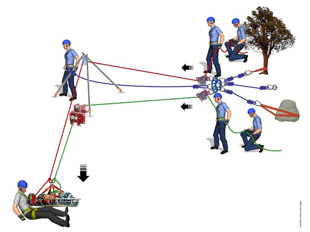
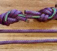
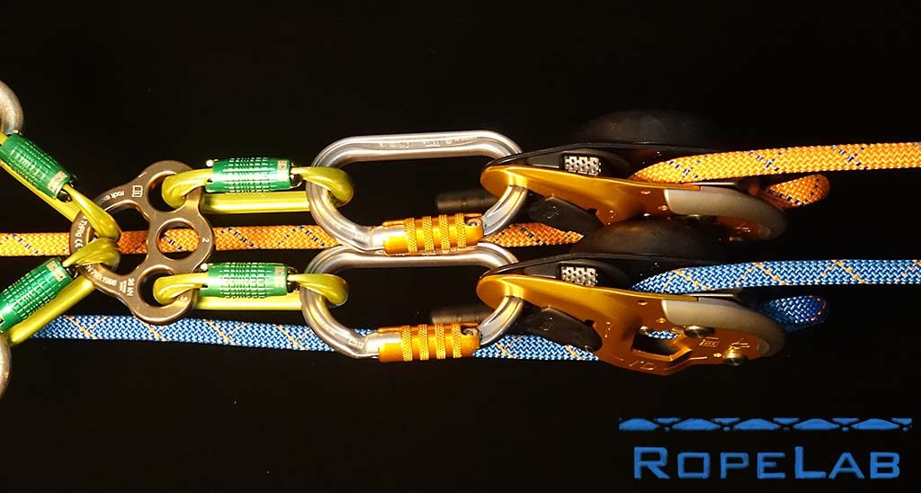
Systems like the one shown above, while functional, make it very difficult to match the tension in the two ropes. It is common to observe big swings from 90/10 to 10/90 between the two as the operators attempt to match each other’s rate of lower.
In the RopeLab member report Members: Matching Tension with Mirrored Systems, I discuss the effectiveness of using two Petzl IDs operated by a single operator and found that, even with attempts to mismatch, the tensions never deviated outside 60/40 – 40/60.
Backup Belayer
A common and valid criticism with having a single operator controlling both lowering devices is that THAT person is a single point of failure in the system. I touch briefly on this consideration in the free article: Redundancy in Rope Systems.
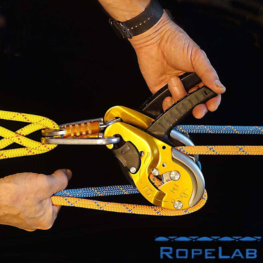
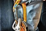
Many rock-climbing instructors are very familiar with the use of an extra person, or backup belayer, behind the primary belayer. This person acts in the same way as a bottom-belayer by providing a fireman’s belay should the operator lose grip with their brake hand.
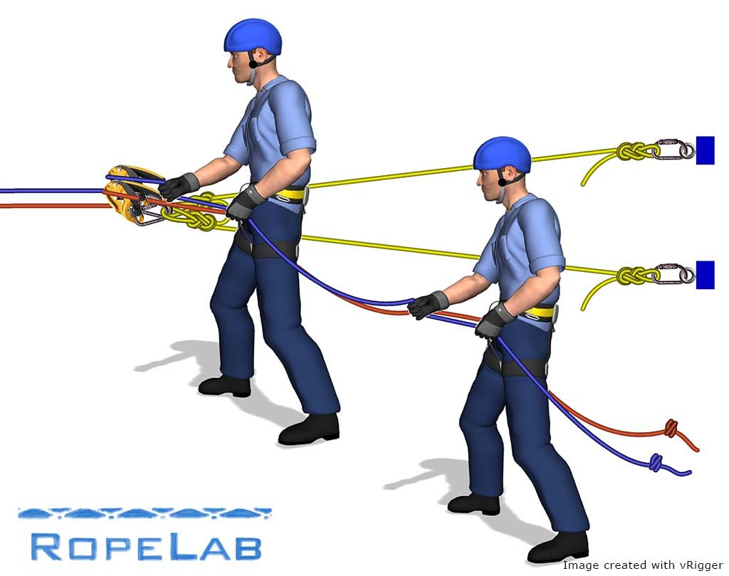
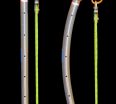
In this image, the second person simply tails both the orange and blue ropes and maintains a small amount of slack in the strands running forwards to the primary operator. Their primary task is to ensure the brake strands are managed and, in the unlikely event that the main operator loses control of the lowering devices, hold on tight. Their secondary task is to clear tangles and warn the main operator as knots or other obstructions approach.
The backup belayer provides appropriate redundancy to ensure there is no single person of failure in the system. This is demonstrated clearly in the following short video.
Operation of dual main systems
There are many ways to configure parallel devices but the main consideration should be the ability of a single operator to manage two devices comfortably.
Many assume that a rigging plate will keep things better organised and provide some separation between components.
Having done this, others then strive for better orientation of the devices by adding extra carabiners, or connectors that incorporate a 90 degree twist.
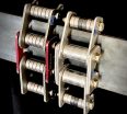
Having tried all of these, I must say that, as usual, the simplest option is still the best.
This simplest option connects the two devices straight to the anchor legs and saves the need for rigging plates and special purpose connectors. It also allows the two devices to self-orientate and sit snuggly against each other without impeding operation. It also works directly attached to a technician’s harness for dual main descents.
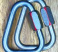
Inline or Twist
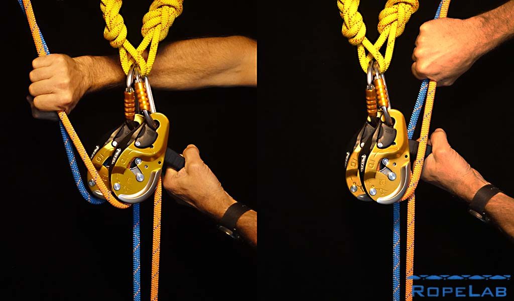
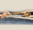
This image shows two possible positions for the brake strands. Both work fine. Many people opt for the one on the right because it has been assumed that the brake rope should be positioned so that it runs over the curved front plate of the device. This option actually forces the rope to take a spiralling path as it passes through the device and this often places twists in the rope.
My preferred option is to have the brake strands exiting on the opposite side of the device (the left option in the image). This has two benefits. Firstly it does not twist the rope as it takes an ‘inline’ path similar to that of brake racks or bobbin type devices. Secondly, this path keeps the moving rope away from the plastic handle of the device and removes the potential for melting or damage to the handle.
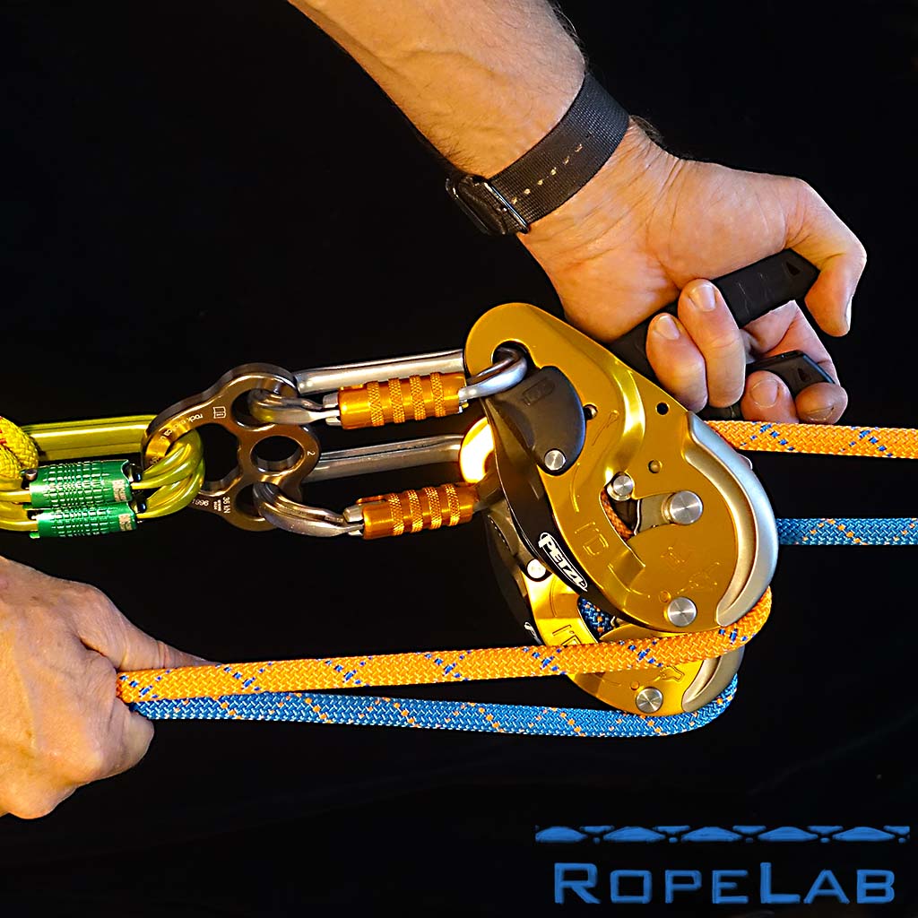
Brake strand position
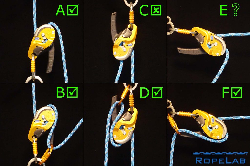
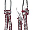
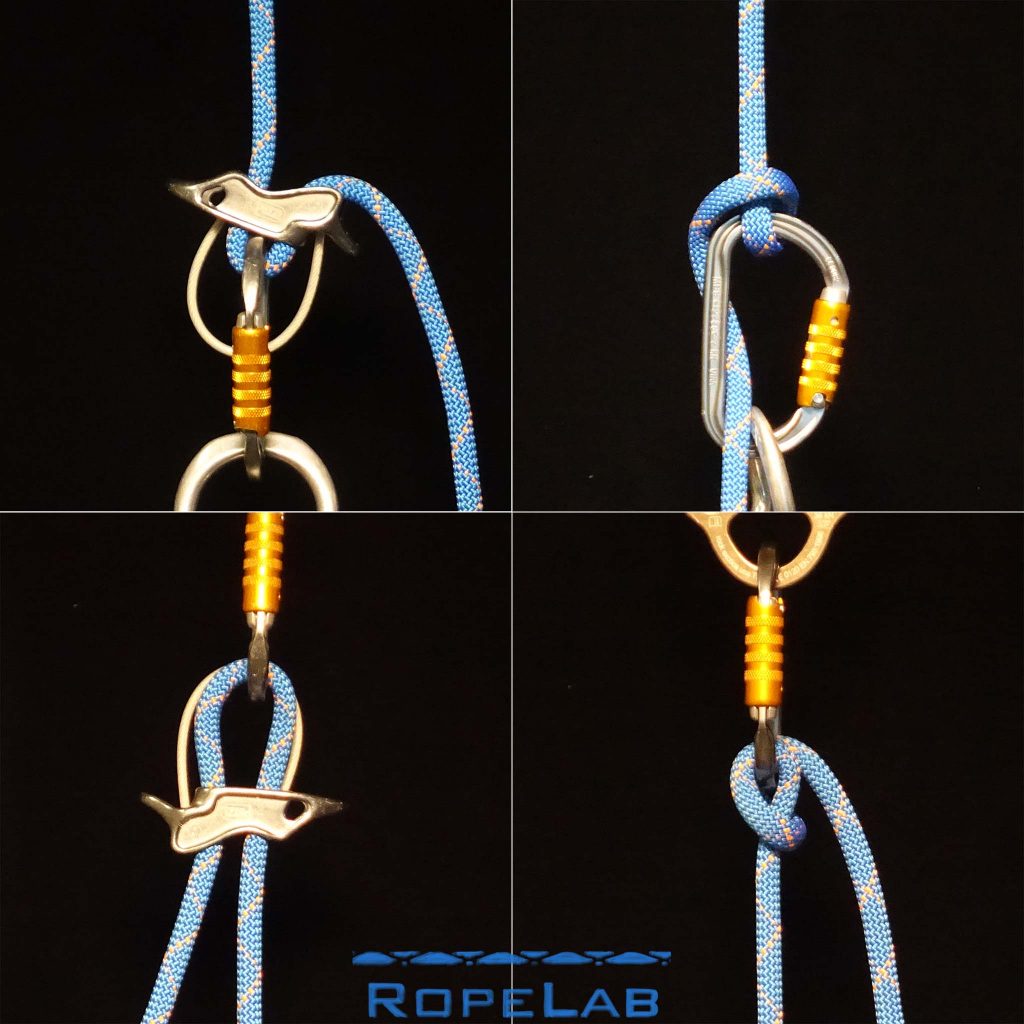
The consideration of brake strand position during operation is not always obvious. In their instructions, Petzl show two options:
- “Device on the harness” – option A in the image above.
- “Device on an anchor” – option D in the image above.
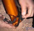
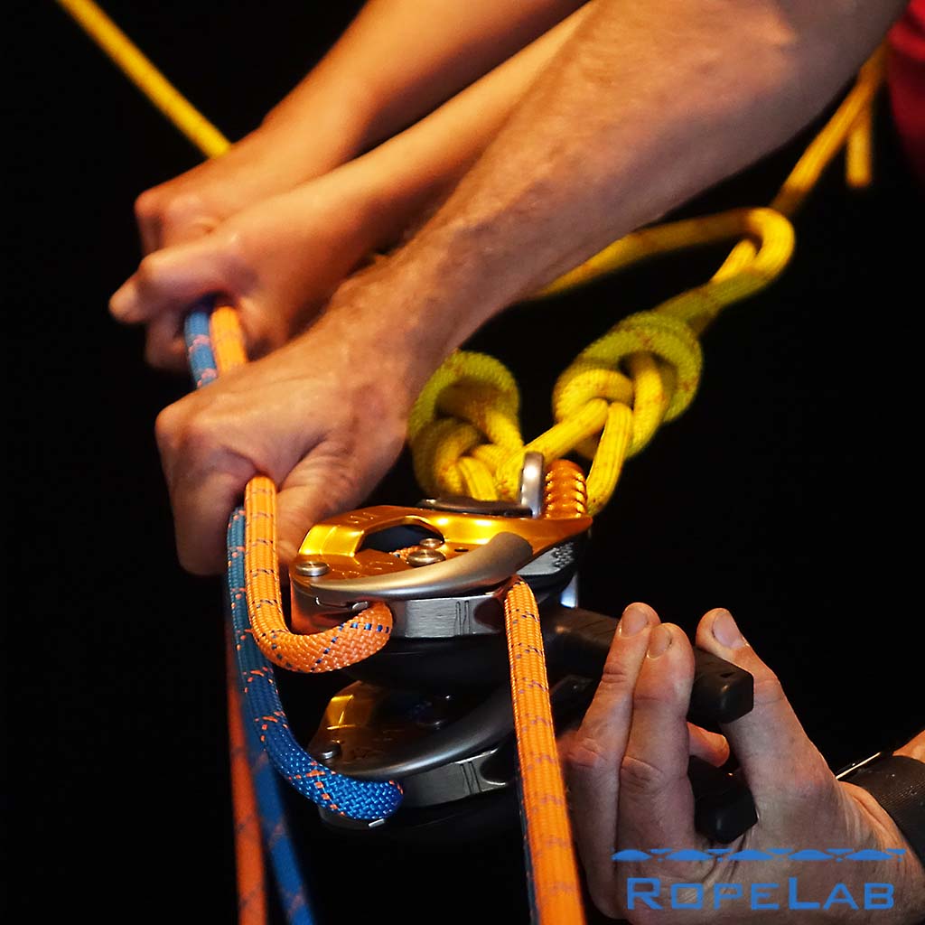
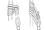
Before discussing option E, consider the following image.
The image shows a tubular belay device and a Munter (or Italian) Hitch. Users have long understood the significance of the position of the brake strand and how this influences the performance of the device. Perhaps this knowledge is less common now as we see, for example, CMC Rescue highlighting the importance of ensuring the “S-shaped” bend in the rope and even warning that “At no point should the running end of the rope have an angle of less than 90 degrees to the load end of the rope”.
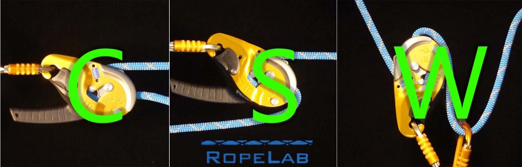
So, with regard to option E above, I would say:
- The brake rope must always be managed behind the device (gravity ensures this with option A), the extra carabiner ensures this in option D). We generally do not want the rope to take a “C-shaped” bend.
- When mounted horizontally and in a way that allows comfortable operation standing behind the device, the extra carabiner may not be required, so long as the operator understands that the rope must take a complete “S-shaped” bend.
- In training it is best to keep it simple so include the extra carabiner.
- In dual main systems operated by a single operator, each device should only see half of the load. Thus the extra carabiner will not be needed for friction, it purely ensures the rope is behind the device. Should the dual main system suddenly become a single rope system, the extra carabiner will probably be needed for friction as well.
- If the extra carabiner is needed for friction, then the brake strand can be also be held forwards so the rope takes a “W-shaped” bend.
Conclusion
Dual main systems are becoming more and more common in both Rope Access and Rope Rescue. Devices that can be positioned back-to-back and operated by a single technician facilitate much better equalisation of tension however, they are dependant on that single operator getting it all right.
For this reason alone, dual main lowering systems should always have some form of backup in place. The simplest way to provide this backup is employing a second technician to act as a backup belayer, tailing both ropes directly behind the primary technician.
© Richard Delaney, RopeLab, 2019


About The Author
Richard Delaney
Richard Delaney has worked professionally with ropes since 1992 as a multi-pitch rock-climbing instructor, technical rescue instructor and rope access technician. Understanding and teaching the Physics of Rigging is a core passion of Richard’s, one based on his experience, and his prior professional life as a qualified engineer.
Add a Comment
You must be logged in to post a comment.
In this configuration should we use a braking beaniers as per manufacturers technical notes?
Also if using ids or idl’s do we need them again in dual main lines?
Hi Charlie,
Always follow the manufacturer instructions.
The decision to use the extra biner or not will depend on the load and the orientation of the device. I normally train teams to get the attendant out of the system if possible.
If it is a 2-person load then you should be able to assume split loading between the dual mains. However, you should always have the biner there in case you are reduced to a single line and need to complete the lower.
I’m afraid I don’t really understand the second part of your question…
Richard
Thanks for your reply, don’t worry about the second part, you answered it for me. Thanks again
Hi Richard, Any thoughts on how a dual main comprising two descenders sits with with IRATA’s requirement for a ‘safety line’ with a ‘back-up device’, where they state in the ICOP: ‘An example of an appropriate standard for back-up devices is EN 12841, Type A’. I guess I probably should be asking this question of IRATA!
Excellent question Will. I’d have to re-read the ICOP to work that out. I know we have put much effort into the re-write of SPRAT’s Safe Practices doc to specifically cater for Dual Main systems.
Hi Richard,
Clutch and iD have the panic system. In this case , two devices need the tail control person?
Yes, always.
I propose that systems should have no single point or person of failure. It is possible for a single person to hold the handles in the open position and let go of the brake ropes. Therefore I always use a second person to tail both ropes.
Richard
Hi Richard,
Thanks for your reply.
https://www.youtube.com/watch?v=cTOgoq6H2ng&t=31s
How about Third scenario? ASAP system instead of tail break man.
Sure, the ASAP can work very well there however my preference is still another person. There will always be enough people there and this job does not require a high level of skill. They also help with any knots or tangles in the ropes.
OK I see.
Your preference option is always tail man. If possible.
So, Two PCD control men they individual operator own PCD. Is need the one tail man?
CMC , Second scenario.
My absolute preference: one person operating two devices with one backup belayer.
If there are 2 people operating 2 devices, a backup belayer is not necessary, but helpful to match tensions.
Great Thanks.
Hi Richard,
I’ve just been working with a team doing a large number of dual main lowers, with long descents and quick turnovers required between participants. We were using CMC Clutches and even though the rope path was straight we still got a degree of rope twist, which caused the occasional short delay in resetting, due to the limited space available. Interestingly, the twist was in a different direction on each line.
I wondered whether you knew of any ropes which are more resistant to twisting. I remember we used to have some lanyards at work with a braided core which was woven to the sheath at intervals. I can’t remember the name of it now.
Thanks for any advice you may have on rope selection.
All the best,
Eddy.
Hi Eddy,
Sometimes you may find that changing the direction the tail enters the device slightly can change the twist direction.
If they were ropes that had been used previously, perhaps running them through other devices with heavy loads left a twist there.
Similarly, as people “coil” ropes different ways they can become twisted.
I have not had much success with rope that have core strands occasionally braided into the sheath as these can feel like “speed bumps” as the sheath bunches slightly.
I don’t really know a good solution – other than pre-flaking ropes carefully and having an attentive tailer who is ensuring twists are clear before they get to the operator.
Richard
I can’t remember the name of the rope, but it was on the Heightec Tensor lanyards.
Thanks Richard,
And thanks for all the great articles. Such a good site.
All the best,
Eddy