


Carabiner Specifications
There is a standard language used in the technical specifications of carabiners but this is not well understood. This article is an attempt to clarify some common markings that appear on carabiners. It should be noted that there is significant industry and international variation in the common use of these terms.
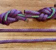
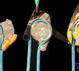
Direction of pull arrows
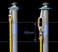
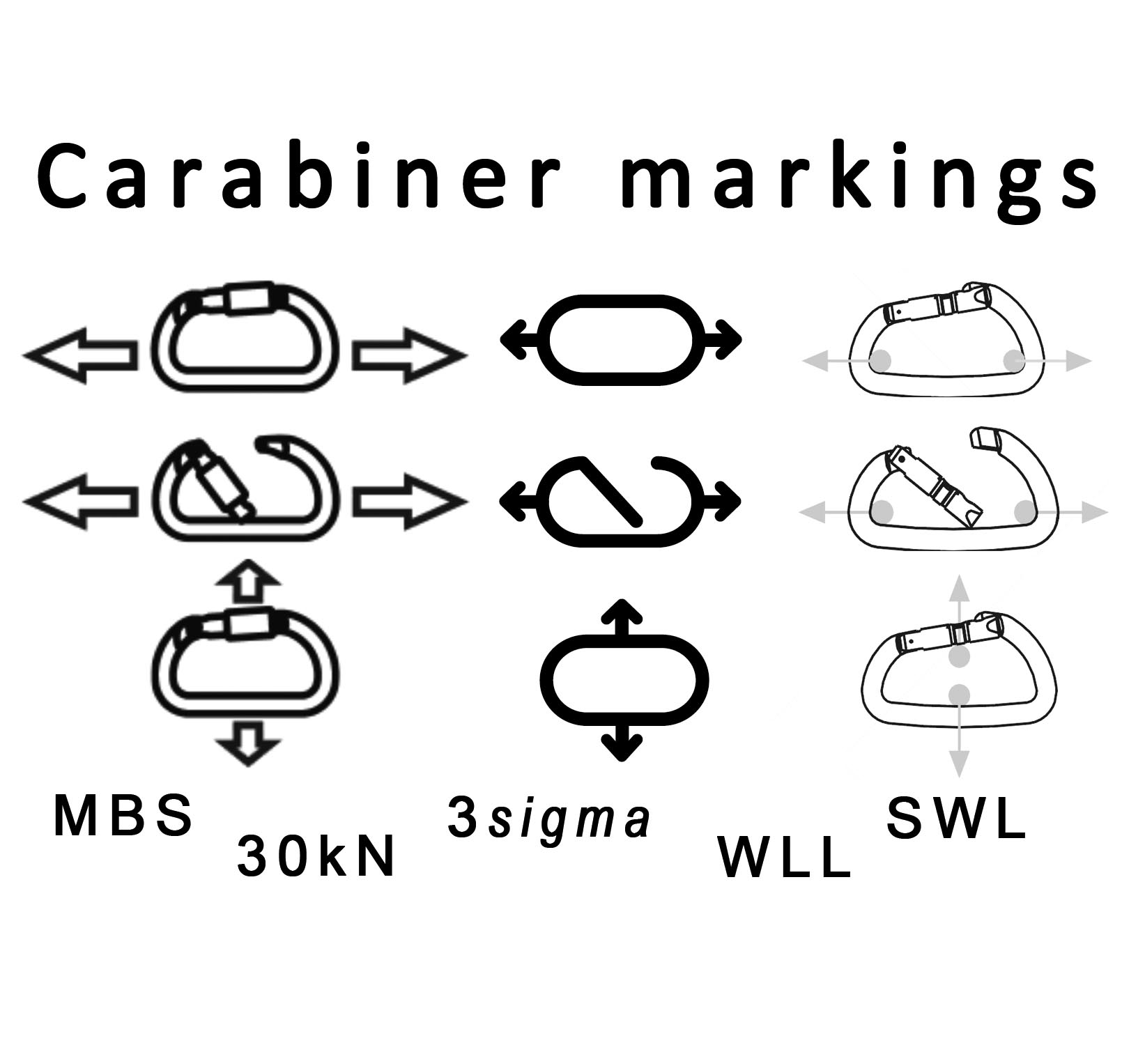
This image from the UIAA (http://www.theuiaa.org/upload_area/files/1/UIAA121-Connectors_2.jpg) demonstrates the test methods for the ratings typically seen on carabiners.
There are typically three sets of arrows indicating strength when pull tested between parallel pairs of round pins for:
- Gate closed, long axis strength when pulled between 12mm pins.
- Gate open, long axis strength when pulled between 12mm pins.
- Gate closed, short axis strength when pulled between 10mm pins.
The stated values are only for these test conditions and these will differ once slings or other hardware are used in place of these pins.
30kN
Values such as 30kN indicate a tensile force in kilo-Newtons (kN). It most commonly refers to the MBS for a specific direction of pull. Users often find it easier to convert this force value to an equivalent suspended static mass value. To achieve this, convert 30kN to 30,000N. Given the relationship Force = Mass x Acceleration, dividing 30,000N by 10 (approx. 9.81 m/s/s for acceleration due to gravity) produces the static equivalent mass of 3,000kg.
MBS & 3 sigma
The Minimum Breaking Strength (MBS) is a statistically derived value and is poorly understood.
If 100 carabiners are submitted for destructive testing then the measured strengths will vary considerably. Inconsistencies in the manufacturing process may result in larger variations. The batch test results can be plotted on a histogram showing the probability of breaking at particular strengths and this curve should approximate a “normal distribution” or “bell curve”.
The width of the curve is characterised by the “standard deviation” or σ (sigma). 3σ for a normal distribution indicates that 99.7% of samples should lie within the range of (mean – 3σ) to (mean + 3σ). Smaller values for σ indicate that samples are more likely to be close to the average, or mean value.
Many carabiner manufacturers state that they use “3-sigma” to determine their MBS values. This means that the MBS is actually the mean breaking strength less 3 times the standard deviation (3σ).
MBS = mean – 3sigma
Statistically, this also means that 0.3% of samples will lie outside this range and therefore half of these (0.15% or 1.5 in every thousand) may break below the MBS stamped on the carabiner.

The curves above show three scenarios, each with a mean tested value of 30kN. Click on the image to see an enlarged version.
- σ = 0.5kN. MBS = mean – 3σ = 30kN – 3 x 0.5kN = 28.5kN
- σ = 1.0kN. MBS = mean – 3σ = 30kN – 3 x 1.0kN = 27.0kN
- σ = 1.5kN. MBS = mean – 3σ = 30kN – 3 x 1.5kN = 25.5kN
Even though the mean value for all tests was 30kN, the MBS for each batch is quite different.
With more and more people undertaking their own testing, it is important to acknowledge that measured values well above the MBS do not necessarily correspond to a well manufactured product. In fact 99.7% of test samples should break above the MBS. If the test samples are from a well controlled manufacturing process with a small σ value, then measured values may not be much above the MBS. If, however, the recorded values are well above the MBS then this may indicate a large σ value, and thus a conservative MBS to cover a poor process.
Maximum acceptable load in normal use
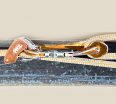
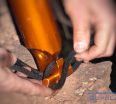
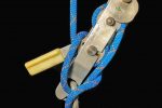
Material behaviour under load is normally characterised by stress vs strain curves. Two terms that are useful in describing this behaviour are Elastic and Plastic Deformation. When an carabiner is stressed by applying tension along the spine it will begin to ‘stretch’ at a relatively low force. If the carabiner returns to its ‘normal’ shape once the stress is removed then we can describe this stretching as ‘Elastic Deformation’. As the stress becomes more significant this ‘stretching’ may enter an irreversible range known as ‘Plastic Deformation’. This image shows a carabiner that failed above its MBS during a pull test. The hinge pin pulled through the host however the body has definitely undergone plastic deformation.
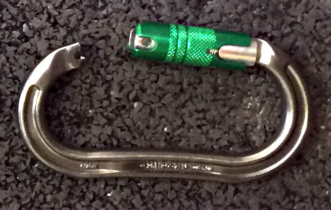
So, carabiners should not fail below their MBS however they will undergo irreversible deformation before reaching this point. Also, it is perfectly reasonable to expect that repeated heavy loading will fatigue the material and result in failure below the MBS.
The question that should come out of this discussion is:
“How much can we load a carabiner without resulting in plastic deformation or significant fatigue?”
Some manufacturers address this explicitly in documentation stating that connector loading should never exceed 1/4 of the MBS.
Design Factor
The Design Factor (DF) is specified by a designer or manufacturer and this defines the factor applied to the MBS to determine maximum load acceptable load for a component.
Safety Factor
Safety Factor (SF) or Factor of Safety (FoS) is generally defined by industry rather than manufacturer. It may be significantly different to DF. For example, a particular connector may have an MBS of 50kN, a manufacturer specified DF of 4, but an industry specified SF of 10 when used for a particular application.
WLL
Working Load Limit (WLL) is a term used by manufacturers to indicate the maximum force that should be applied to a carabiner in normal use, regardless of industry. The ratio of MBS to WLL is referred to as the Design Factor (DF). Many carabiner manufacturers specify a DF of 4 which implies a WLL of a quarter of the MBS. Manufacturers state the WLL to ensure that the carabiner is not subjected to significant fatigue and remains in the range of normal elastic deformation.
WLL = MBS / DF
SWL
Safe Working Load (SWL) is typically determined by dividing the MBS of a carabiner by the Safety Factor (SF) required for a particular use. As stated above it possible that an entertainment rigger may calculate a different SWL for a particular use of a carabiner than the value determined by a rescue technician.
SWL = MBS / SF
Example
A particular steel carabiner has a 3-sigma rated long-axis MBS of 50kN. The manufacture has specified a DF of 4 for this connector, regardless of use.
This carabiner has a WLL of 12.5kN and this value should never be exceeded in normal use – regardless of industry or application. If this value is exceeded it should not fail below the MBS however it should then be removed from service and destroyed.
An entertainment rigger, working in a certain country is required by the industry code-of-practice to use a SF of 10 for flying performers and thus, determines the SWL of this carabiner is 50kn/10 = 5kN.
A rescue technician in another country is supposed to apply a SF of 5 to hardware and thus determines a SWL of 50kn/5 = 10kN for an identical connector.
Eduardo José Slomp Aguiar has been kind enough to translate this article into Portuguese. We are grateful for his input. The Portuguese translation can be found here.
© Richard Delaney, RopeLab 2015


About The Author
Richard Delaney
Richard Delaney has worked professionally with ropes since 1992 as a multi-pitch rock-climbing instructor, technical rescue instructor and rope access technician. Understanding and teaching the Physics of Rigging is a core passion of Richard’s, one based on his experience, and his prior professional life as a qualified engineer.
Add a Comment
You must be logged in to post a comment.
When you talk about “pins” do you mean anchors ? Please explain ?
Hi Chris,
I’ve now included an image from the UIAA which shows the standard test method.
The significance is that the stated values have been obtained under these test conditions. Standard tests are not performed on carabiners for objects such as wide slings.
This is why I’ve done some of the tests written up in other reports and suggest that the stated MBS should be de-rated significantly for wide slings and basket slings with sling angles of up to 60 degrees.
I think I finally understand the 3sigma idea!
I’ve heard an alternate definition of SWL/WLL though and would be interested on everyone’s input.
WLL is the limit given to us by the manufacturer using the object in standard configuration where as SWL is derived by the user when using the object in alternate acceptable configurations. I’ve seen this on the tags of crane slings where the strength of the sling for a straight pull is labelled WLL and then baskets and chokes are listed as SWL.
I’ve also come across the term Design Factor (DF) related to WLL which fits your comment Scott. A similar expression can be used as the one we use for SWL relating to Safety Factor (SF).
WLL = MBS / DF
SWL = MBS / SF
I’ve updated this article today to include more details about SWL and WLL.
What do you do when a product you use doesn’t have a prescribed DF?
Eg: http://www.edelrid.de/en/sports/safety-super-ii-11-mm-snow.html and http://www.edelrid.de/out/documents/downloads/GAL_Static_Ropes.pdf
(I’m aware anecdotally that “rope manufacturer’s have a Design Factor of 4” but have not seen this published)
Also, this product’s documentation refers to a “Max. Breaking Strength (kN)” instead of “Minimum Breaking Strength (MBS)”. Are these interchangeable? Or am I missing something?
Hi Dylan,
I’d be fairly confident that that is a misprint in the edelrid specs. It should be Min not Max.
As for DF, 4 is a good default assumption however this will normally be less that the SF we apply.
It is going to be very interesting to see where the FoS discussion goes in the next few tear as I think we have overcomplicated things be trying to apply a general SF to components without having to de-rate for specific uses.
I have been told that edelrid specifies a DF of 4.
Richard